Inverter circuit Using Transistors
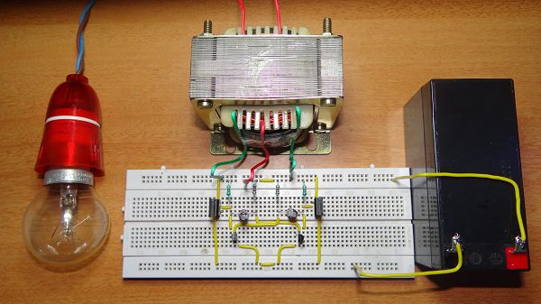
A 12V DC to 220 V AC converter can also be designed using simple transistors. It can be used to power lamps up to 35W but can be made to drive more powerful loads by adding more MOSFETS.
The inverter implemented in this circuit is a square wave inverter and works with devices that do not require pure sine wave AC.
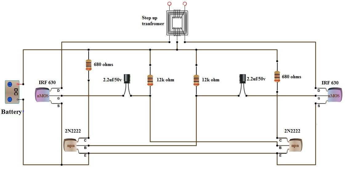
Circuit Diagram
Components required
- 12v Battery
- MOSFET IRF 630 -2
- 2N2222 Transistors
- 2.2uf capacitors-2
- Resistor
- 680 ohm-2
- 12k-2
- 12v-220v center tapped step up transformer.
- 2N2222 Datasheet
- IRF630 Datasheet
Working
The circuit can be divided into three parts: oscillator, amplifier and transformer. A 50Hz oscillator is required as the frequency of AC supply is 50Hz.
This can be achieved by constructing an Astable multivibrator which produces a square wave at 50Hz. In the circuit, R1, R2, R3, R4, C1, C2, T2 and T3 form the oscillator.
Each transistor produces inverting square waves. The values of R1, R2 and C1 (R4, R3 and C2 are identical) will decide the frequency. The formula for the frequency of square wave generated by the astable multivibrator is
F = 1/(1.38*R2*C1)
The inverting signals from the oscillator are amplified by the Power MOSFETS T1 and T4. These amplified signals are given to the step-up transformer with its center tap connected to 12V DC.


Comments
Post a Comment